
Keeping Power Quality Utility-Friendly Saves Energy Usage & Operating Costs
Utility power providers have started taking a proactive approach to enforcing power quality standards for permissible harmonic content. When oil producers have poor power quality and harmonic non-compliance, utilities are now telling them to mitigate the offending harmonic content from the producing equipment or face having their power turned off and their producing wells shut in.
What should you do?
The Lifting Solutions field harmonics measurement and analysis service is a way of validating existing power quality standards at the well site for harmonic distortion. The objective of this client-collaborative analysis is to understand the application and power demands and then design a strategy for reducing line-side harmonic content on incoming power systems. Ultimately, improving power quality at the well site, keeping you producing while in compliance with your utility, and saving you money on your power bill is our goal.
Oilfield Site Evaluation
Lifting Solutions field service engineers evaluate oilfield well sites for harmonics and power quality using a Fluke Model 435 Series II Power Quality Analyzer. Then, they perform a post analysis on the data using several different software packages including Fluke Power Log II and analysis software that includes Easy Harmonics and ETap. Finally, a solution and strategy centered on hard-number ROI and reduced energy usage is proposed.
To learn more or to start a well site evaluation, contact your LSI Client Solutions representative.
Field Harmonics Measurement & Analysis
The purpose of field harmonics measurement and analysis is to develop and design strategies that reduce incoming line-side harmonic content on power systems while paying attention to power cost savings for operating oilfield equipment.
Utility power providers are starting to take a proactive approach and enforce their own power quality standards for permissible harmonic content. In cases of poor power quality, producers will receive a notice from their utility power provider (with a grace period) to install appropriate equipment to mitigate offending harmonic producing equipment or face having their power turned off and their producing wells shut in. The principle goal of the Lifting Solutions (LSI) field harmonic measurement and analysis service is to collaborate with our clients to understand and plan for strategies and applications that provide harmonic compliance that meets utility power quality standards and the economics of capital cost. Any harmonic solution proposed will be centered on ROI (based on the reduction of utility energy and billings usages) from installing LSI harmonic mitigation equipment.
Main Theory
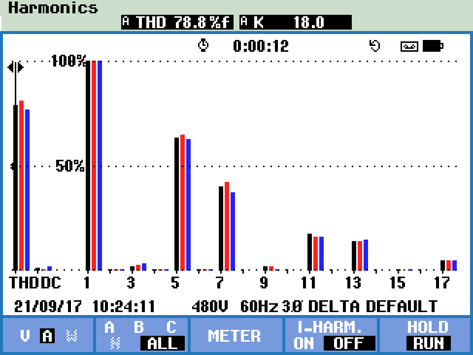
Harmonic mitigating systems or filters are designed with the goal of reducing harmful harmonic currents created using nonlinear loads. In our clients’ cases, nonlinear loads would be variable frequency drive (VFD) systems used on their oilfield production systems. VFDs are known to create current or I-THD harmonics of up to 70% of the utilized current (see Figure 1).
The relationship of these I-THD harmonic or distortion currents can be expressed as a basic model equation:
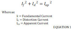
For oilfield clients, the capital cost of harmonic mitigation must have a corresponding return on investment as part of the installation strategy. By reducing I-THD distortion currents, we should be able to reduce the apparent current with appropriate harmonic mitigation filtering strategies in place to values close to the fundamental amount of current, thereby increasing system efficiency and lowering operational power costs.
When our clients decide to use and operate VFDs on their oilfield production equipment, their line-side power factors are often measured from 0.50 to 0.95 for VFD units. This delay in power utilization is not generated in the same manner as power factor from a motor or other inductive load on sinusoidal power. This is caused by the delay in conduction on the rectifiers on the VFD input bridge to charge the DC bus inside the VFD back up to RMS value of the voltage on the incoming line. Currents do not flow until the voltage on the line breaks over the DC bus level. Depending on the amount of energy consumed from the VFD DC bus, power is pulled from the input utility line only at the peaks of the waveform. This is the inverse of a standard linear load, which is why a lightly loaded VFD or an oversized VFD will almost always show a poor power factor as opposed to a fully-loaded or properly sized VFD.
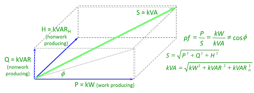
Power factor for VFDs cannot be corrected in the usual standard manner with the addition of power factor correction capacitor banks (PFCC); this will increase the chance of resonation in the system creating harmful resonate runaway currents. To properly correct this situation, a tuned shunt in the filter should be used. The result is reduced distortion power factor and reduced overall current used. The equation for the power factor calculation can be seen in Figure 3 (these are simplified mathematic models).
While different theories for calculating energy gains and losses from nonlinear loads exist, none of them seem to fit overall. Lifting Solutions selected an overall modest and the most applicable model to calculate gains. Field studies and trials offer the best overall performance markers to create a better ROI model. In theory, if we reduce the overall level of distortion in the system, we should be able to reduce the overall current required to operate the system.
Oilfield Site Evaluation Process
Oilfield sites are usually proposed by our clients and relayed to LSI Automation field services engineers. Our engineers use the Fluke Model 435 Series II Power Quality Analyzer to take measurements for use in the harmonics assessment study. The well sites are then tested for harmonic distortion and full power quality analysis. Several software packages are utilized for the post-analysis of all the Fluke 435-II data; these packages typically include the Fluke Power Log II and analysis software that includes Easy Harmonics and ETap.
As most harmonic filter programs are designed around harmonic content and total harmonic distortions, they do not cover gains in efficiency or reduced power demands. As this is a primary goal and deliverable for LSI, a modified approach is required so that the evaluation process determines ROI based on net savings from the utility billing and metering usage.
To learn more or to initiate an evaluation on your well site, contact your local LSI Client Solutions representative.